Circuit
The puzzle consists of a series of pictures: a large printed circuit board, a set of resistors with colored bands, and a set of cables with five-letter words written on them. We are also given a small “sample wiring” board with cables and resistors already in place. We start here to figure out how the pieces of our larger board should come together.
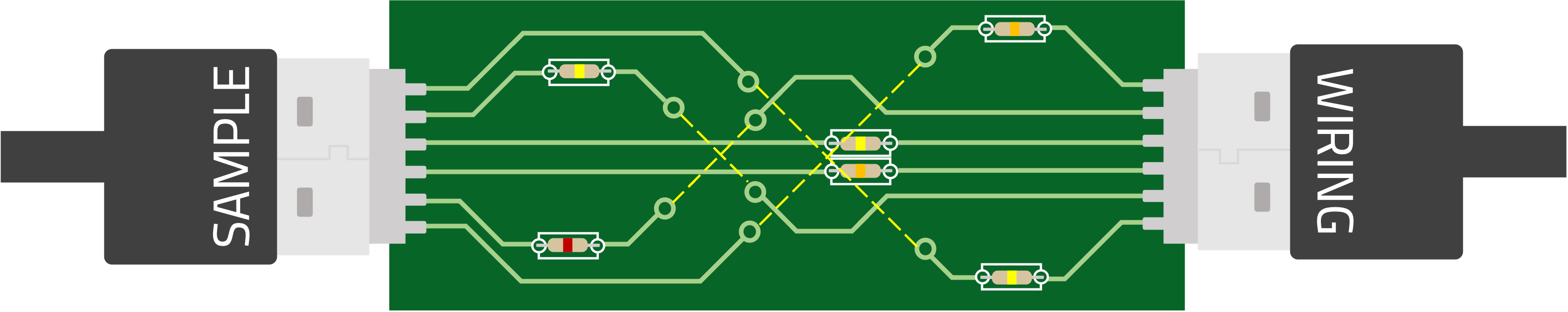
Both SAMPLE and WIRING have six letters and six traces (light green lines) coming out from the port where their cable is plugged in. The large board has just five traces for each of its ports, so we guess that each trace carries one letter. Using this interpretation, we see that the sample connects P directly to R through a yellow resistor, and M to I through an orange resistor. The other connections are a little less clear: the traces disappear into vias (small light green circles), and it’s hard to tell where they should reappear. One potential interpretation that works is: whenever a trace disappears, its letter keeps going in the same direction until it reaches another via whose trace is coming from the opposite direction. This would be nice because it works coming from both directions, and looking at the big board confirms that such connections are always possible. Using this interpretation, we can look at all the connections from the sample board (invisible connections illustrated with a dotted yellow line below).
Sample chip laid out.
While trying to figure out what the resistors could mean, we might consider resistor color codes, which would map the five resistor colors in this puzzle to 1-5 respectively. We might also look at the difference between the connected letters. If we do this, we’ll see that each resistor color always goes with the same letter difference, and that all letter differences are powers of 2.
From here, we discover that resistors flip the nth bit in the binary representation of a letter, where n is the number associated with that resistor’s color. For example, a red resistor (corresponding to the number 2 in the electronic color code) would flip E (which is 00101) to M (which is 01101).
| Letters | Resistor Color | Color Code | Letters Diff |
|---|---|---|---|
| S and W | Orange | 3 | 4 |
| A and I | Red | 2 | 8 |
| M and I | Orange | 3 | 4 |
| P and R | Yellow | 4 | 2 |
| L and N | Yellow | 4 | 2 |
| E and G | Yellow | 4 | 2 |
Now we move onto the big board (it’s okay if we don’t totally understand everything yet; there’s some more break-ins here). One good place to start is the upper left corner, where the last two letters of one word are the first two letters of another (in the opposite order). This can only be WEIRD and DREAM or WEIRD and DRAFT, and if we understand how letters jump across vias, we also see the E in weird become the other word’s third letter, so these must be WEIRD and DREAM. The resistor then goes between an I and an A, so it must be red.
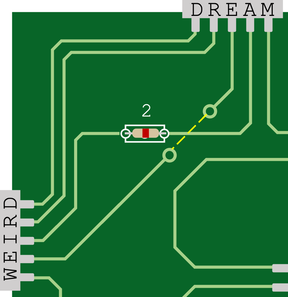
Upper-left fragment of the main board break-in.
We might also look at the center port at the bottom of the board, whose second and fourth letters are connected through a resistor. The only given word for which this is possible is PRIZE, which makes that resistor red.
But we have to figure out what’s going on with the chips on the PCB board. We can look at the left side of the board, where one input port connects all five of its letters to one chip (one through a resistor, and one on the side opposite the others). Not many given inputs could lead to a valid word on the bottom of that chip; the only two are
- LEASE with a red resistor could give us SMAL? with ????E on the other side;
- SPACE with a yellow resistor could give us CRAS? also with ????E on the other side.
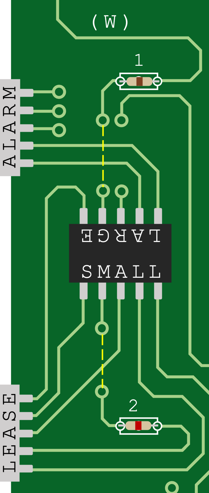
Antonyms break-in from another fragment of the main board. The numbers above the resistors (which correspond with the electronic color code) indicate which bit is flipped, for convenience.
After placing LEASE and ALARM, the next easiest word to place is STING in the lower-left to get BIRTH on the nearby chip, using similar logic to before. In general, we can spread out from connections by seeing what letters a given letter could turn into (there’s never more than 5) and which input words have such a letter in the appropriate spot. In this way, we can eventually fill in all of the resistors and inputs from our bank; there is only one way to place them such that the green LED ends up with a valid word, and this arrangement is shown below.
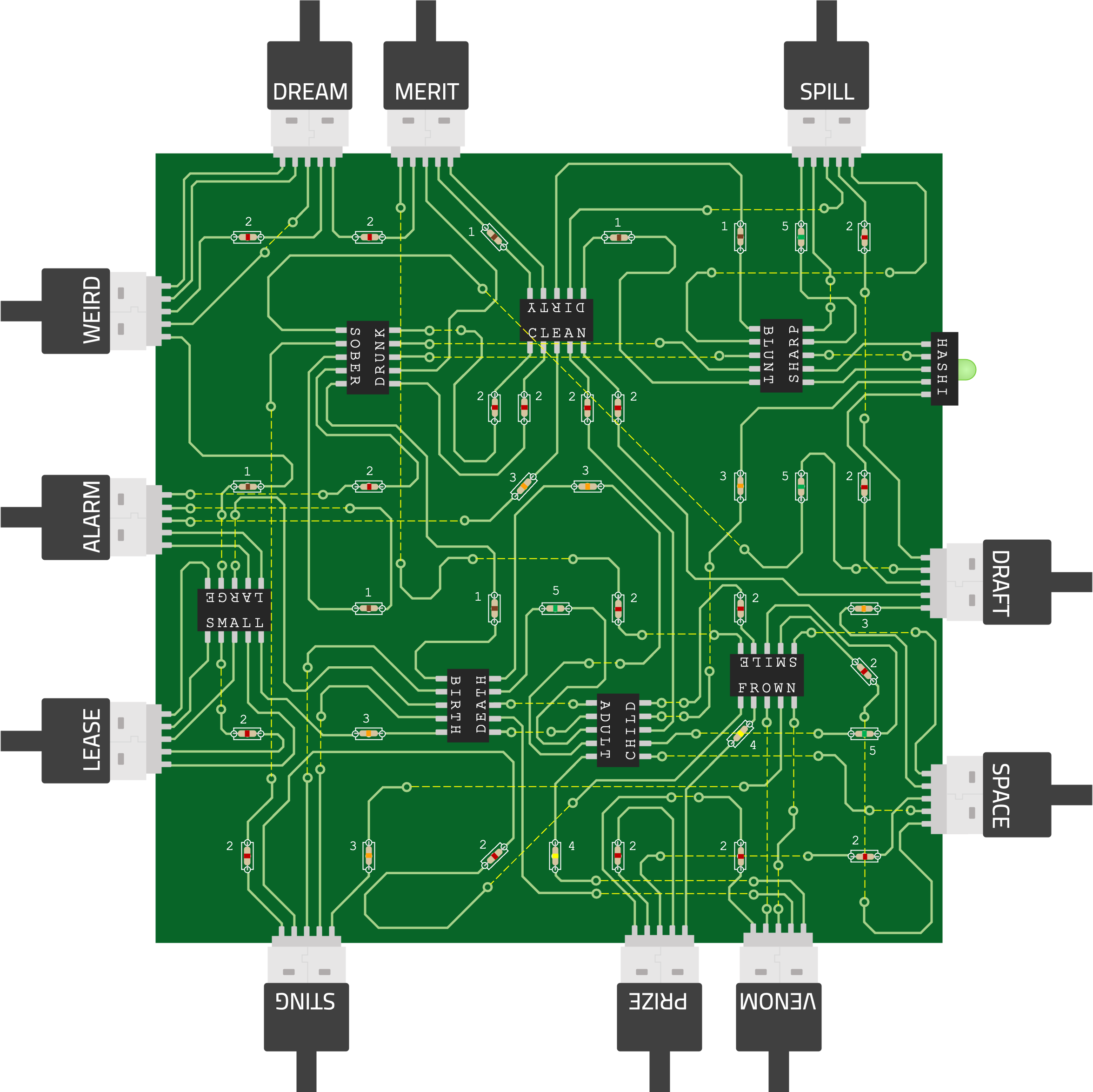
Completing the main board.
The green LED's word is HASHI: a type of logic puzzle in which you connect numbered dots with lines. Our PCB board has dots under each resistor, and now that we’ve placed our resistors, each dot is associated with a number 1-5. Our next step is to solve the Hashi puzzle (shown below).
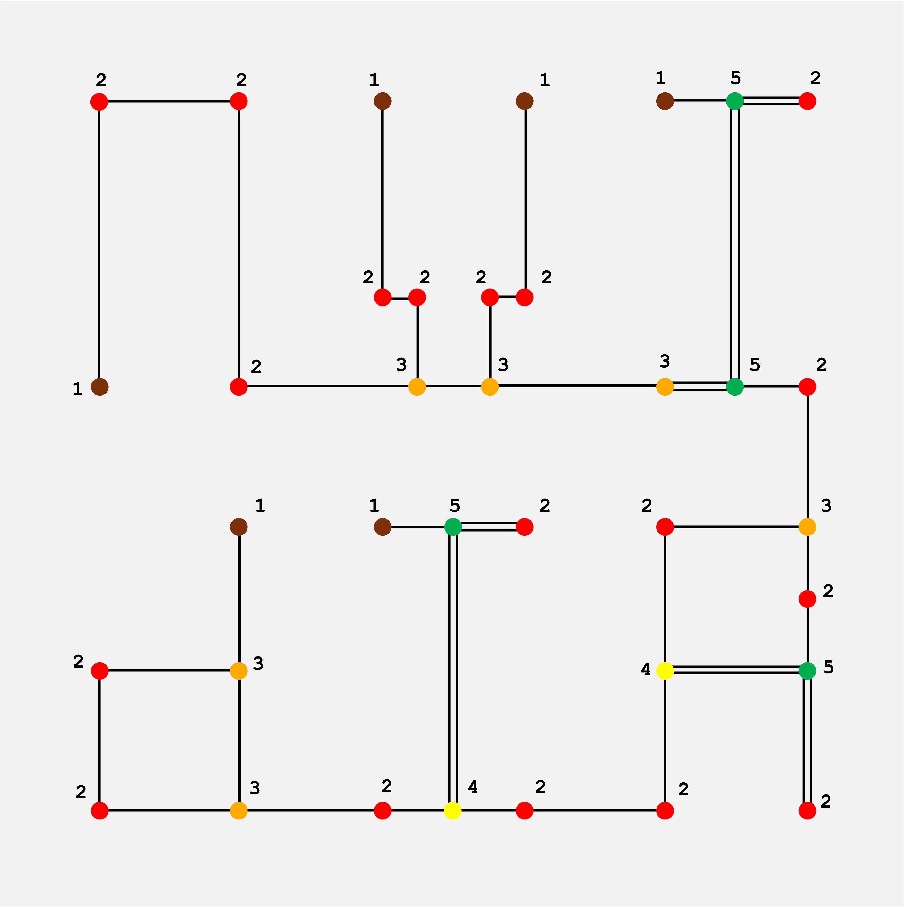
Solution to the Hashi subpuzzle.
The lines of our solution draw out our answer: NVIDIA.