 RUBIK
RUBIK Our Fates Are Interlocked (Solution)
by John Stumpo; interface by Gary Wang
This is a simulation of a railroad interlocking machine (Union Switch and Signal Model 14) and corresponding interlocking plant. Here is a diagram of the interlocking that is simulated:
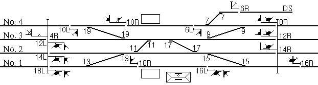
(Symbol key - this diagram was made from another diagram on that site.)
Interlockings consist of switches and signals controlled by levers. The signals in this interlocking are visible, and they are of the classic all-amber Pennsylvania Railroad position-light type. The switches, however, are hidden. Their location, and which lever controls which one, must be determined by how they influence the signal aspects when thrown and from which levers become locked in place when switches are thrown. The point of interlocking is to prevent any manipulation of the levers that would create an unsafe situation, such as sending a train through an improperly lined switch, creating a combination of routes that could cause a collision, or moving a switch that a train might be moving over.
Levers have at least two states, normal (N) and reversed (R). Some signal levers on a Model 14 control a pair of signals and have states normal (N, in the center), left (L), and right (R). A signal lever in normal position prevents the signal from clearing - the signal displays the Stop Signal aspect (rule 292). Reversing a signal lever allows the signal to display something other than Stop Signal. A switch lever leaves the switch (or the two switches of a crossover) lined for straight-through movement when normal and for the diverging (or crossover) move when reversed. By convention, signal levers are even and switch levers are odd.
The lights under the levers indicate which moves are possible to make in the interlocking's current configuration. If a lever is locked out (a switch lever that is locked in its current position or a signal lever that cannot be moved to some position), the light goes out.
Which lever (and direction) goes to which signal is easily discoverable by just moving each signal lever both ways and seeing which signal clears. All except 6R will clear if all switches are normal. Since this is so easily done, and the real challenge is dealing with the switches, I didn't bother concealing the signal numbers in the HTML page. (The id attributes for the signal images include the signal number.)
Some switch locations can be determined by changes in signal aspect. For example, 12R clears to Slow Approach (Clear if 4R is cleared) if switches 11 and 19 are normal, Restricting if 11 is reversed, and Medium Clear if 11 is normal and 19 is reversed. This indicates that the route from 12R is determined by switches 11 and 19, and that 11 is reached before 19. But the main workhorse in determining where the switches are is in the interlocking logic, and the puzzle can still be solved with the only knowledge of signal aspects being the difference between a Stop Signal (which is what everything starts out as) and everything else.
There are three main ways in which the switch layout is discoverable via the interlocking logic. First, signals cannot be cleared if they would permit a train to hit an improperly lined switch. (For example, throwing 19 will prevent signal 10R from being cleared, indicating that 19 obstructs the route from 10R.) Second, switches cannot be thrown if there is currently a route signaled over them. (For example, signal 8R can be cleared with switch 9 in either position, but 9 becomes unthrowable when 8R is cleared, indicating that the route from 8R uses switch 9.) And third, signals can only be cleared in one direction at a time over a given route - otherwise we might get a head-on collision! (For example, having switch 9 reversed, 11 normal, and 19 normal connects track 4 to the east with track 3 to the west. The signals for this route are 8R and 12L. With the switches lined that way, it is possible to clear either one of those signals - but not both. This indicates that those signals control the opposing moves over that route.)
Then the schedule comes into play. It provides a sequence of moves through the interlocking that take place one after another. For each train, take the minimum set of levers that must be out of normal position for the move to take place. Add the lever numbers to the given offset, and the sum is a number in the range [1,26] - an index into the alphabet. Doing this for each train on the schedule spells out the phrase (spaces added) "FIRST LETTER OF TWENTIETH FOURTH FIRST AND SIXTEENTH STATIONS TO WEST SEE BLOCKSTATION DOT NET". (This is 80 letters from 80 trains, and the train directions, interpreted as binary 8-bit ASCII, spell out "REDHERRING", indicating that they have nothing in and of themselves to do with the solution; this also covers the direction the signal levers must be moved to properly route the trains, since there is a 1:1 correspondence between signal lever direction and train direction.)
(Note that some moves go to or from P1 and P4, which are signaled pockets adjacent to passenger platforms. This permits other trains to "leapfrog" trains that are stopped at the platforms. The list of moves does take into account whether or not these locations are currently occupied by trains, and when a 1-1 or 4-4 move is indicated that would go through an occupied location, the "leapfrog" move (for example, 19-9-8R) is expected. Think of the P as standing for "Pocket" or "Platform".)
| Direction | From | To | Levers | Lever Sum | Sum | Letter | |
|---|---|---|---|---|---|---|---|
| ← | 4 | 2 | (-22) | 11 9 8R | 28 | 6 | F |
| → | 2 | 1 | (-20) | 15 14L | 29 | 9 | I |
| ← | 4 | 4 | (+0) | 10R 8R | 18 | 18 | R |
| → | 2 | 4 | (-15) | 9 11 14L | 34 | 19 | S |
| ← | 1 | 2 | (-11) | 15 16R | 31 | 20 | T |
| ← | 1 | 4 | (-55) | 19 17 15 16R | 67 | 12 | L |
| → | 4 | 4 | (-11) | 6L 10L | 16 | 5 | E |
| ← | 1 | P1 | (+4) | 16R | 16 | 20 | T |
| ← | 4 | 2 | (-8) | 11 9 8R | 28 | 20 | T |
| → | 4 | 1 | (-56) | 15 17 19 10L | 61 | 5 | E |
| ← | 1 | 3 | (-34) | 4R 17 15 16R | 52 | 18 | R |
| ← | 1 | 4 | (-52) | 19 17 15 16R | 67 | 15 | O |
| ← | 1 | 1 (leapfrog) | (-38) | 13 15 16R | 44 | 6 | F |
| → | P1 | 1 | (+4) | 16L | 16 | 20 | T |
| ← | 3 | 3 | (+7) | 4R 12R | 16 | 23 | W |
| → | 2 | 4 | (-29) | 9 11 14L | 34 | 5 | E |
| ← | 3 | 3 | (-2) | 4R 12R | 16 | 14 | N |
| → | 3 | 1 | (-24) | 15 17 12L | 44 | 20 | T |
| ← | 4 | 1 | (-32) | 13 11 9 8R | 41 | 9 | I |
| ← | 4 | 3 | (-16) | 4R 9 8R | 21 | 5 | E |
| ← | 2 | 3 | (-15) | 4R 17 14R | 35 | 20 | T |
| → | 4 | P4 | (-2) | 10L | 10 | 8 | H |
| ← | 1 | 4 | (-61) | 19 17 15 16R | 67 | 6 | F |
| ← | 3 | 4 | (-16) | 19 12R | 31 | 15 | O |
| ← | 4 | 3 | (+0) | 4R 9 8R | 21 | 21 | U |
| → | 3 | 1 | (-26) | 15 17 12L | 44 | 18 | R |
| ← | 3 | 4 | (-11) | 19 12R | 31 | 20 | T |
| ← | 3 | 3 | (-8) | 4R 12R | 16 | 8 | H |
| → | 2 | 1 | (-23) | 15 14L | 29 | 6 | F |
| ← | 4 | 2 | (-19) | 11 9 8R | 28 | 9 | I |
| ← | 4 | 2 | (-10) | 11 9 8R | 28 | 18 | R |
| ← | 4 | 1 | (-22) | 13 11 9 8R | 41 | 19 | S |
| ← | 4 | 4 (leapfrog) | (-16) | 19 9 8R | 36 | 20 | T |
| → | 2 | 1 | (-28) | 15 14L | 29 | 1 | A |
| ← | 1 | 3 | (-38) | 4R 17 15 16R | 52 | 14 | N |
| ← | 3 | 4 | (-27) | 19 12R | 31 | 4 | D |
| ← | 4 | 2 | (-9) | 11 9 8R | 28 | 19 | S |
| → | 2 | 1 | (-20) | 15 14L | 29 | 9 | I |
| ← | 2 | 2 | (+10) | 14R | 14 | 24 | X |
| → | 2 | 2 | (+6) | 14L | 14 | 20 | T |
| ← | 3 | 3 | (-11) | 4R 12R | 16 | 5 | E |
| → | 1 | 1 | (-29) | 16L 18L | 34 | 5 | E |
| ← | 1 | 2 | (-17) | 15 16R | 31 | 14 | N |
| → | 1 | 1 | (-14) | 16L 18L | 34 | 20 | T |
| ← | 3 | 4 | (-23) | 19 12R | 31 | 8 | H |
| ← | 1 | 2 | (-12) | 15 16R | 31 | 19 | S |
| → | 2 | 4 | (-14) | 9 11 14L | 34 | 20 | T |
| ← | 2 | 4 | (-49) | 19 17 14R | 50 | 1 | A |
| ← | 4 | 1 | (-21) | 13 11 9 8R | 41 | 20 | T |
| → | 1 | 1 | (-25) | 16L 18L | 34 | 9 | I |
| ← | 1 | 4 | (-52) | 19 17 15 16R | 67 | 15 | O |
| → | 4 | 1 | (-47) | 15 17 19 10L | 61 | 14 | N |
| ← | 3 | 3 | (+3) | 4R 12R | 16 | 19 | S |
| ← | 3 | 4 | (-11) | 19 12R | 31 | 20 | T |
| → | 1 | 1 | (-19) | 16L 18L | 34 | 15 | O |
| ← | 4 | 3 | (+2) | 4R 9 8R | 21 | 23 | W |
| ← | 4 | 1 | (-36) | 13 11 9 8R | 41 | 5 | E |
| → | 3 | 3 | (+7) | 12L | 12 | 19 | S |
| ← | P4 | 4 | (+10) | 10R | 10 | 20 | T |
| ← | 3 | 3 | (+3) | 4R 12R | 16 | 19 | S |
| → | 2 | 4 | (-29) | 9 11 14L | 34 | 5 | E |
| ← | 4 | 4 | (-13) | 10R 8R | 18 | 5 | E |
| ← | 4 | 4 | (-16) | 10R 8R | 18 | 2 | B |
| → | 1 | 3 | (-30) | 11 13 18L | 42 | 12 | L |
| ← | DS | 4 | (-8) | 10R 7 6R | 23 | 15 | O |
| → | 1 | 4 | (-48) | 9 11 13 18L | 51 | 3 | C |
| ← | 2 | 4 | (-39) | 19 17 14R | 50 | 11 | K |
| ← | 4 | 4 | (+1) | 10R 8R | 18 | 19 | S |
| → | 2 | 1 | (-9) | 15 14L | 29 | 20 | T |
| → | 1 | P1 | (-17) | 18L | 18 | 1 | A |
| → | 3 | 1 | (-24) | 15 17 12L | 44 | 20 | T |
| ← | 3 | 2 | (-14) | 11 12R | 23 | 9 | I |
| ← | 3 | 2 | (-8) | 11 12R | 23 | 15 | O |
| → | 4 | 3 | (-15) | 19 10L | 29 | 14 | N |
| ← | 3 | 4 | (-27) | 19 12R | 31 | 4 | D |
| ← | 2 | 1 | (-12) | 13 14R | 27 | 15 | O |
| ← | 4 | 3 | (-1) | 4R 9 8R | 21 | 20 | T |
| → | P1 | 1 | (-2) | 16L | 16 | 14 | N |
| → | 1 | P1 | (-13) | 18L | 18 | 5 | E |
| → | 1 | 4 | (-31) | 9 11 13 18L | 51 | 20 | T |
This indicates that solvers should go to blockstation.net and figure out where the reference point is. Looking through the diagrams, it will be found that the interlocking that is simulated matches up with the main segment of Overbrook interlocking, in the "Zoo to State (Main Line - Philadelphia to Harrisburg)" section. There are 58 diagram pages in all on the site, many of which do not contain any interlockings, which I don't think is too unreasonable to have to look through.) Overbrook is also a commuter station - note the station platforms on the diagram. Counting the indicated numbers of stations west of there (using either the diagrams or a list of stations on the SEPTA Paoli/Thorndale Line as it exists today) gives Downingtown, Ardmore, Merion, and Paoli, whose first letters spell DAMP, which is the answer. (The only difference between the diagrams and the line as it runs today, as far as placement of commuter stations is concerned, is that the western terminus, Thorndale, is not on the diagrams, as it was built later. It is a little west of Thorn interlocking.)
The filenames of the signal graphics used on the puzzle page are the rule numbers in the NORAC Operating Rules (which apply to the railroad this interlocking is on) that specify each signal aspect. This is not critical to solving the puzzle, but serves as a suitably obscure way to provide extra confirmation of what the graphics actually are, since the files have to have names of some kind anyway. Other rulebooks are likely to have similar corresponding rule numbers, should solvers happen to be familiar with (or stumble across while Googling) some other rulebook.